How to Pick and Connect a Raspberry Pi 5 Camera Cable

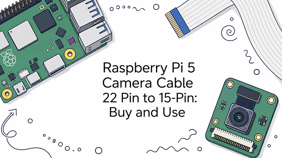
The Raspberry Pi 5 camera cable you need is a 22-pin, 0.5 mm pitch to 15-pin, 1 mm pitch flat flexible cable (FPC). It comes in 200 mm, 300 mm and 500 mm lengths. Plug the 22-pin end into one of the Pi 5's camera ports and the 15-pin end into your camera. At each connector, line up the bare metal contacts with the contacts inside the socket, then close the latch. Your camera's own cable will not do this job.
The problem is that the Pi 5 uses smaller connectors than older Pi boards. The ribbon in the box of most camera modules is a 15-to-15 type, so it either refuses to fit or fits badly. Many people push harder, bend the ribbon, or order a display cable that looks identical and does nothing for a camera.
This guide walks through four steps: match the cable to your camera, connect it in the right orientation, test it in software, and fix the usual faults. Vadzo designs MIPI CSI-2 camera modules with driver support for the Raspberry Pi 5, so the connector details matter to us as much as they do to you.
Why the Raspberry Pi 5 Camera needs an adapter cable
The Pi 5 uses a small 22-pin camera connector, while most camera modules still use a 15-pin one, so you need an adapter cable between them. The cable converts one pitch and pin count to the other.
What changed on the Pi 5
The Pi 5 has two four-lane MIPI connectors, and each can carry either a camera or a display. They use the 22-way, 0.5 mm "mini" FPC format that the Compute Module IO board and the Pi Zero series already used. Older full-size Pi boards and most camera modules use the wider "standard" format.
Connector | Pins | Pitch | Where you find it |
|---|---|---|---|
Standard | 15 | 1 mm | Older full-size Pi boards, most camera modules |
Mini | 22 | 0.5 mm | Pi 5, Pi Zero series, Compute Module IO board |
A 15-to-15 ribbon cannot connect to a Pi 5, so you need a 22-to-15 adapter.
Camera cable or display cable
The camera adapter and the display adapter have the same pair of connectors, but they are not interchangeable. A camera cable does not work with a DSI display, and a display cable does not work with a camera. Look for the word CAMERA printed on the cable body before you buy or plug anything in.
Step 1. Match the cable to your camera
Count the pins on your camera's connector. A 15-pin camera needs a 22-to-15 cable, and a 22-pin camera needs a 22-to-22 cable.
Identify the camera connector
The 15-pin FPC is visibly wider than the 22-pin one. Raspberry Pi's own modules and many third-party boards use 15 pins. Some boards, such as the Arducam IMX708 autofocus camera, have a 22-pin connector and take a 22-to-22 cable. Check the product page or the board silkscreen. Do not guess from the camera's name.
Bolt-series cameras from Vadzo are bare boards. The Bolt-234CGH, for example, is listed from $190.00, and that price does not include the lens or the cable. Confirm the connector and pinout on the product page before you order a cable. For OEM builds, Vadzo can also supply a custom cable length and connector type.
Choose the length
Pick the shortest cable that reaches without a tight bend. Standard 22-to-15 adapters run from 200 mm to 500 mm and usually cost a few dollars.
Length | Best for |
|---|---|
200 mm | Camera right beside the Pi in a compact case |
300 mm | The safe default, with slack to reposition the camera |
500 mm | Camera on a separate bracket, gimbal or housing wall |
As a worked example, say your camera sits 15 cm from the port. The cable has to cover that distance plus a gentle curve at each end, so 200 mm is tight and 300 mm is the better pick. Do not chain two cables to gain length, because MIPI is a high-speed signal. Buy the length you need.
Step 2. Connect the cable to the camera port
Shut the Pi down, open both latches, slide each end in straight with the contacts facing the socket contacts, and close the latches. The Pi 5 sockets are small, so work slowly.
Connect each end in the right orientation
Shut down the Pi and unplug the power supply.
Choose a port. The Pi 5 labels them CAM/DISP 0 and CAM/DISP 1. Either works for a camera.
Lift the small latch on the Pi 5 socket with a fingernail.
Slide the 22-pin end in straight, with the bare contacts facing down toward the board. Contacts facing up is wrong.
Press the latch closed so it grips the ribbon.
Repeat at the camera. On Raspberry Pi modules the bare contacts face the camera's circuit board. Some third-party boards use top-contact sockets, so look at the socket first.
Check that the ribbon sits square and fully seated, with no gap at the latch.
If the cable resists, stop and reseat it instead of pushing harder.
Protect the ribbon
A creased or torn ribbon causes intermittent faults that look like software bugs. Keep bends gentle, never fold the cable flat against the connector, and give it some strain relief if the camera will vibrate.
Step 3. Test the camera in software
Boot Raspberry Pi OS and ask the system to list cameras. If your camera appears, the cable and connection are good.
Run the detection commands
Current Raspberry Pi OS ships the rpicam tools. Run these in order:
rpicam-hello --list-cameras rpicam-hello -t 5000 rpicam-still -o test.jpg
The first command lists detected sensors. The second opens a five-second preview. The third saves a still image. Official Raspberry Pi modules are detected automatically.
Add a driver for other sensors
A third-party sensor may need an overlay line in /boot/firmware/config.txt, followed by a reboot. Use the overlay name from your camera maker. Add ,cam0 if you used port 0:
dtoverlay=<sensor_name>,cam0
Vadzo ships sample applications and integration guides with every evaluation unit. Follow them for the exact driver steps for your module.
A camera that shows up in the list proves the cable, the orientation and the driver are all correct.
Step 4. Fix problems with the connection
Most failures come from a half-seated ribbon, the wrong orientation or the wrong cable type. Check those three before you suspect the camera.
Diagnose by symptom
Symptom | Likely cause | Fix |
|---|---|---|
No cameras available | Ribbon not seated or flipped | Power off, reseat both ends, check contacts |
Cable will not fit the Pi 5 port | 15-to-15 cable | Use a 22-to-15 adapter |
Nothing works with a new cable | Display cable bought by mistake | Look for CAMERA printed on the body |
Detected but no image | Wrong overlay or port | Match cam0 or cam1 to the port you used |
Flickering or dropouts | Creased or long cable | Swap in a fresh, shorter cable |
Swap in a known-good cable before you blame the camera.
When the cable is not the problem
If the cable is correct and the camera still fails, the cause is usually the driver or the sensor's support on the Pi 5. Check that your kernel and overlay match the sensor. If you use a Vadzo camera, the support team helps with systems that will not detect it.
Plug in the right cable and get a clean image
Buy a 22-pin to 15-pin adapter in the shortest length that reaches. Check the CAMERA print, seat both ends with the contacts facing the sockets, and confirm the camera in rpicam-hello --list-cameras. Most connection problems end at one of those steps.
If you are building a product around the Pi 5 and need a camera that works without custom driver work, explore Vadzo's MIPI camera modules. The application engineering team can help you choose a sensor, lens and cable.